
I like Triumph cars.
I like computers.
I should REALLY like tinkering with a computer IN a Triumph car.
Lets find out...........
Why would you want a computer in an old car?
The best example of WHY I wanted to do this conversion was seen when I was setting up the timing for my car.
As I was driving up and down my "test track", I was getting pinking/pinging around 1300 to 2000 rpm and 70 to 80 kPa. By listening to the motor and watching the electronic dashboard, I could see exactly "where" the pinging was happening and could change the timing in that particular spot!

As you drive, there is an indicator that shows where on the chart the computer is reading from. I was getting pinging in the area of the black rectangle. Using a 7inch tablet as my "dashboard", I would stop the car, touch the screen and reduce the timing from say 22 down to 20 then drive it again. Eventually it ended up like above with 11s and 12s instead of the original 16s and 28s.
Try doing THAT with distributor weights and springs!
That is one reason WHY,
now how do you do it???
That is one reason WHY,
now how do you do it???
First of all you need a brain. ECU. Electronic Control Unit.
Megasquirt or some other ECU?
Bit of a "no-brainer". I don't have $3000 for just the ECU, that's more than I paid for the car!
However, don't expect ANY help from a regular local shop or a regular local mechanic.
You are on your own with all the other Forum members. Just pray they pay their internet bills!
There is a ship-load of info out there, you just have to find and filter it.
This
why I thought I would write this blog. There are some great sites out
there with terrific info & lovely photos, but they often left me
with more questions. Hopefully I can fill in some gaps here.
Which Megasquirt?
If there was EVER to be a "next time", it would NOT be an MS1 again for me, regardless of price.
This
is purely down to a few software features of the MS11. Out in the
boondocks of sunny Australia, you have to make do with what parts you
can find, so being able to EASILY set up different brand temperature
sensors and have them correct is one less major pain to learn how to do.
The
Ezytherm conversion program for the MS1 requires re-booting,
re-flashing, typing in code type stuff. It is too "old-school DOS" for
me. Drop-down menus RULE!
I also believe you can configure MS11 to leave the cooling fans off while cranking. Having my 2 fans running whilst trying to start a hot, problematical car, drained the weak battery all too often.
I also believe you can configure MS11 to leave the cooling fans off while cranking. Having my 2 fans running whilst trying to start a hot, problematical car, drained the weak battery all too often.
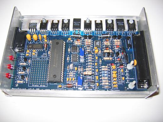

MS11 is easily recognisable by the extra PCB shown in the red rectangle compared to the MS1 above.
Do you know what this is....
Do you know what this is....

If you do not fully comprehend (or want to know) how this diagram relates to this photo.....

DON'T buy a secondhand (or kit form) Megasquirt!!!
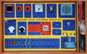
I knew about transistors and diodes, I had a "50-in-One kit as a kid!
You WILL need to know much more and many people will help, but understanding their help can be a different matter.
Pay the difference and get your Megasquirt made up to your specifications and you will be much happier. My little knowledge gave me a false sense of security.
I paid about 150 Aussie dollars for a "bargain" MS11, when a new assembled kit was about 400AUD
Whoops, it was a MS1! (Let the buyer beware).
There are "millions" of combinations of how to setup your Megasquirt to work with your particular engine. This ECU can run any engine from a whipper snipper to a F1 engine.
It just needs to be configured by soldering wires from here to there, adding/removing some little "do-hickies". Some "do-hickies" have to go in the right way and some don't.
I spent nearly a year trying to track down why I couldn't get the cooling fans to operate via the MS unit. Eventually I understood the help that I was receiving.....
it seems you have 12v for the flyback return at the top diode (D9 yes?) if that is the case with the miss wired SPR3 you would have applied 12v to the processor output pin. That pin I fear is probably now dead, unfortunately. Dave's test by applying 5v to the resistor feeding the TIP's base will likely confirm this if it switches the relay.
I did manage to "fry" the pin, probably very early on and no matter what I did would it ever work.
If I had the MS built, I would not had misunderstood that I really did have to build the fan control circuit for a MS1 and then stuffed up the wiring and blew up the pin, causing MONTHS of delays and mega-frustrations.

If I had the MS built, I would not had misunderstood that I really did have to build the fan control circuit for a MS1 and then stuffed up the wiring and blew up the pin, causing MONTHS of delays and mega-frustrations.
BATTERY. BATTERY. BATTERY.
Buy a big new one!
A HUGE problem I had was not being able to get a RPM signal. For months I wrestled with all sorts of scenarios , re-reading all the MS forums on why there was no RPM signal.
If the megasquirt does not pickup a RPM signal, nothing happens.
I ran into this problem again later in my saga. The motor had been running on the Megasquirt with EDIS and I was attempting to setup the fuel injection. I had not changed any electrical/timing type stuff, just the wet fuelly bits. No RPM signal, no Duty Cycle, no sniff of a kick! Checking the fuses, wiring etc, I read the multimeter whilst cranking to quadruple check there was voltage going to the MS during cranking, and behold 9.5volts cranking! BINGO.
I connected the MS feed wire to another separate 12Vbattery and she roared into life at the first crank! The MS unit requires more than 10V to function. Old battery, old car, old Lucas starter = BIG headache.
SPARK PLUGS.
Yes you need "resistor" type plugs. Why? Who cares? It doesn't work with out them.
Resistor plugs generally have an "R" in their part number.
COIL.
There are at least 2 types of connections on the Ford style coils for the plug leads and they are NOT interchangeable. Just make sure the leads match with the coil.

There are at least 2 types of connections on the Ford style coils for the plug leads and they are NOT interchangeable. Just make sure the leads match with the coil.
The coil I happened to acquire had a different layout to "ALL" the other coils documented on the web, and naturally it didn't work following the "normal" instructions!
After much investigating, I arrived at this....

My coil pack on the left looked for all intents and purposes to be the same as all the others except you will notice that the four pin plug is numbered in the opposite direction and the plug wires (P1 - P6) are a different sequence. With the plug wires correctly sequenced correctly, it fired first pop!

THEN it wouldn't STOP! AGGGGHHHHHH
Another cry for help to the MS forums and the answer came back...... "It actually sounds to me like a problem sometimes seen when you change
older cars over to internally regulated alternators. Usually just cured
with a diode."
True enough, a diode was needed between the alternator and ignition light. Just happened
to have the right one (1N0004) thanks to my previous MS1 problems!!! The engine
now starts AND stops.
Australian Fords do have these type of coils but they are hidden down the back of the engine bay under tonnes of injection manifold casting. When you do find an accesable one, make sure you also remove the "radio suppressor" capacitor. The debate still rages if it is actually needed but it is nigh impossible to buy one over a counter. The internet suggests they look like this...
 but the ones I found at Aussie wreckers were like this.....

Australian Fords do have these type of coils but they are hidden down the back of the engine bay under tonnes of injection manifold casting. When you do find an accesable one, make sure you also remove the "radio suppressor" capacitor. The debate still rages if it is actually needed but it is nigh impossible to buy one over a counter. The internet suggests they look like this...
EDIS or not to EDIS is another question.

"Everyone" says to use one as it is really simple but it would also appear that many users who actually know what they are doing, graduate away from EDIS as their knowledge and experience grows.
I like it because I only have to select EDIS from one drop down menu and it is configured!
Connecting wires into terminal blocks is also easy, just like my old 50 in 1 electronic set!
Connecting the EDIS to the MS wiring loom should be straight forward but I had trouble understanding how and where to wire the "shields".
2 of the loom wires are bundled together and are surrounded by metal foil to protect the signal inside the wire being distorted by outside interferace, Remember the noise that would come through the car radio without a radio noise capacitor?
The shielded loom wires connect to the shielded VR Sensor wires and the actual shields (foil and/or wire) have to be joined together but also only connected at one end.
I think I used PIN7 on the EDIS connection block to join the VR shield and Loom shield together.
Please do your own research and checking on this matter.

VR Sensor & Trigger Wheel.
These are the bits that tell the MS where the piston is so it can work out when to fire the spark plugs etc.
A 36-1 trigger wheel is common, where there are 36 evenly divided teeth around a metal wheel/gear but with one tooth removed. The VR sensor sits very close to the metal wheel and as each tooth goes past, a small electrical signal is created and sent back to the ECU. The ECU notices when there is NO signal (the missing tooth) and now knows exactly where the piston is in its travel.

The trigger wheel does not have to be thick and chunky as in the photo but it does have to be accurately cut and spaced. I am using a pressed metal plate version made by a very helpful MSquirter (TimW) overseas. It is only about 2mm thick and I have bent the teeth over at 90 degrees. Bending the teeth over must be accurate also other wise the sensor maybe too far away.
I can tell you that my tooth bending needed a bit of fine adjustment and you can still see teeth out of alignment while running, but it does run.

Apparently it shouldn't matter which way the VR sensor is wired in, BUT some do have markings showing + & - symbols?????
One of the most common cures suggested for RPM signal problems is to "swap the VR wires over".
It of course didn't work for me (my battery was below 10V cranking) but during investigation and continuity checking of the VR wires, it appeared that somehow/why my VR wires "cross dressed", meaning that the blue wire at the sensor became the grey wire at the other end!!!
I have only found one other example of this on the net, but given most people would wire according to colour, this may explain why "swapping the wires" usually works!
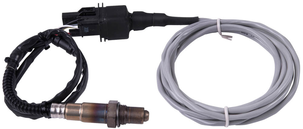
O2 Sensor.
This measures how much oxygen is in the exhaust gas. Too much oxygen means the fuel mixture is lean. The MS reads these signals and adjusts the amount of fuel going into the engine to give the mixture ratio that has been programmed in.
There are Narrow Band and Wide Band sensors.
A narrow band sensor will tell you if the mixture is lean or rich but not by how much!
You REALLY need to know HOW rich or lean the engine is running, especially
There are quite a few wide band sensors out there, usually around $300 plus but I have been using Alan To's Spartan Lambda Sensor and Controller for around $100.
http://www.14point7.com/products/spartan-lambda-sensor

Alan was very helpful during my one small but major hiccup with the sensor.
I didn't take the wring diagram out with me to the car. There were only a few wires, I know where Red and black go!!! NO PROBLEMS!
Red wire = power. Check.
Black wire = ground. Check.
Green wire = ECU. Check.
White wire = Heater. (The heater will need power, therefore wire to 12V)
WRONG!!!!!!!!
The instructions clearly state.... White wire to GROUND.
One of the most common cures suggested for RPM signal problems is to "swap the VR wires over".
It of course didn't work for me (my battery was below 10V cranking) but during investigation and continuity checking of the VR wires, it appeared that somehow/why my VR wires "cross dressed", meaning that the blue wire at the sensor became the grey wire at the other end!!!
I have only found one other example of this on the net, but given most people would wire according to colour, this may explain why "swapping the wires" usually works!
O2 Sensor.
This measures how much oxygen is in the exhaust gas. Too much oxygen means the fuel mixture is lean. The MS reads these signals and adjusts the amount of fuel going into the engine to give the mixture ratio that has been programmed in.
There are Narrow Band and Wide Band sensors.
A narrow band sensor will tell you if the mixture is lean or rich but not by how much!
You REALLY need to know HOW rich or lean the engine is running, especially
There are quite a few wide band sensors out there, usually around $300 plus but I have been using Alan To's Spartan Lambda Sensor and Controller for around $100.
http://www.14point7.com/products/spartan-lambda-sensor
Alan was very helpful during my one small but major hiccup with the sensor.
I didn't take the wring diagram out with me to the car. There were only a few wires, I know where Red and black go!!! NO PROBLEMS!
Red wire = power. Check.
Black wire = ground. Check.
Green wire = ECU. Check.
White wire = Heater. (The heater will need power, therefore wire to 12V)
WRONG!!!!!!!!
The instructions clearly state.... White wire to GROUND.
All is working well now.
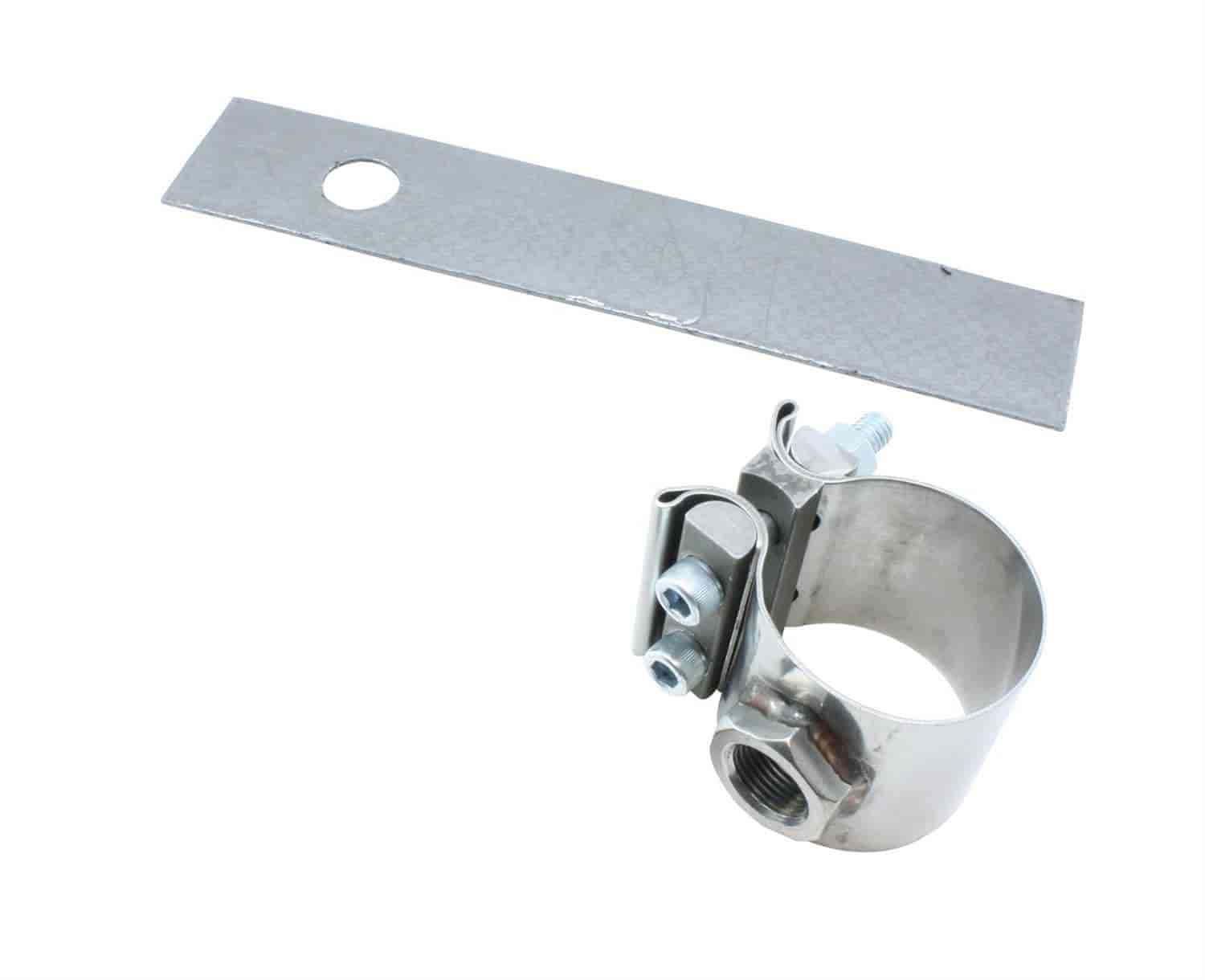
The O2 sensor needs to be close to the engine and on the "top half" of the pipe, rather than dangling down where condensation could run in and cause trouble.
I did find this interesting device to use instead of removing the exhaust and paying someone to weld a bung in.
 AEM No-Weld O2 Sensor Mount
The O2 sensor needs to be close to the engine and on the "top half" of the pipe, rather than dangling down where condensation could run in and cause trouble.
I did find this interesting device to use instead of removing the exhaust and paying someone to weld a bung in.
RELAYS, WIRING & FUSES.
There are some really neat installs out there and this can be one section where your artistic talents can shine through.


I like the newer type fuse blocks where there are red LEDs to show which fuse has blown.


I got one of these that can hold 6 relays.
Relay protection.
VERY simply, when the power is turned off to a relay, there is still some electricity left inside the relay coil. If this escapes it can do damage. Placing a diode (one way electricity valve) in the circuit, will stop the power traveling to where it can do damage.
I think this is referred to "flyback" so just be aware this situation occurs.

Temperature Sensor
The Triumph has a standard coolant sensor with a 5/8" x 18 UNF thread. The GTR185 as well as Lucas: SNB151, 43246; Rover: ADU7161 - late Mini have the same.
Everyone will tell you.... "its the same as the Bosch sensors when you are calibrating the ECU."
Fine if you have a MS11, but with a MS1 you "should" use the Ezytherm program to modify some code of some sort. However, it turned out to be close to the standard figures in MS1.
The thread maybe the same size, but the thread/bolt is loose on the actual sensor. This means although the thread has been tightened, the sensor is loose and able to rotate and slide in and out. About as water tight as the Titanic! I believe the thread is supposed to push the sensor into the mounting hole where the olive on the sensor will mate with a tapered seat. My Triumph does not have a tapered seat! JB Weld has been doing a great job so far holding the thread fast on the shaft!

I started with boiling water in a mug and inserted the GTR185 connected to the MS, a thermometer supplied in a radiator testing kit and a hand held IR thermometer with the probe attached.
The gun read 87, the thermometer read 83 and the MS read 79 degrees C.
This 4 degrees of separation was kept constant across subsequent readings up to 94 and down to 70.
So, which figure is correct? Does it really matter? Watching the engine temperature warm up, it is easy to spot where the thermostat opens. That should be 82C, then whatever MS says (eg. 78) take the variation into consideration when needed. eg. fan control temperatures.
So how do you SEE all this stuff?
Tunerstudio is the software program you instal onto a laptop. The program has all the buttons you need to press, figures to adjust and dials to watch.
You and a mate can be driving down the road programing/adjust/tuning as you drive on real road conditions. You only need to do this to set the ECU up and probably leave it alone for ever, but it is fun to be able to adjust your engine accurately and instantly.
The laptop is connected to the ECU via the old school serial port/DB9 but newer bluetooth connections are taking/taken over.

Typical gauge configuration.
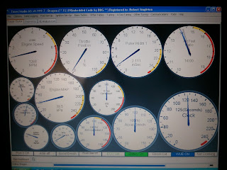
User configured dashboard

Typical configuration window with easy drop down boxes.
The laptop is pretty big and cumbersome. However a bluetooth tablet or phone can now be used as a digital dashboard. I was able to get my 7incher to sit up on top of the dash and dangle down where I could see it.


The white dial backgrounds were way too bright for night driving............

You can change "dashboards" at a "slide" of your finger.

Your log is uploaded to the net then you can view it on a computer using
MegaLogViewer
MegaLogViewer allows you to review how all the readings performed as you were driving along.

This is just a simple example of the records and data available you can review.
MSDROID is another program for Android phones and tablets. MSDroid allows you to actually tune (adjust timing etc) your engine via your tablet instead of using Tunerstudio on a laptop.
Another REALLY cool feature of MSDroid (that seems to have disappeared lately) is GPS logging along with data logging. You should be able to play back your engine data log and in a window next to it should be a map showing where you were at that time on the road (race track!!).

No comments:
Post a Comment